Installing a N2MB WOT BOX - B6 A4, 1.8T
This mod is brought to you by N2MB.com Discuss this mod - Here |
||
| Prior Experience: None |
|
|
| Cost: approx $200 | ||
| Time: 3 hours | ||
One of the newest product developments for the B6 A4 1.8T is the N2MB WOT Box. This device is very simple to install and use, and is creating quite a buzz in the aftermarket scene. The N2MB WOT Box has performs 2 functions. 1) It gives you a 2 stage launch control. This means the box sets an artificial Rev limiter at a pre-programmed value so that when you are setting up for a launch, you do not have to worry about modulating the gas pedal to maintain engine RPM. It also gives you the advantage of building some boost while you are on the line waiting to launch. Launch Control Videos (please right-click, save-as)
2) The WOT Box gives you the ability to Flat Shift. This is also known as No-Lift Shifting. What this means is that you can floor the car, and not take your foot off the gas pedal as you depress the clutch and pull through the gears. The box enables this by cutting spark to the engine for small amounts of (programmable) time during the shift. Flat Shift Video (please right-click, save-as)
|
||||||||||||
How Launch Control Works: The WOT Box enables launch control when you depress the clutch all the way, and then floor the car. It detects clutch position from a clutch switch, and pedal position from the accelerator pedal position sensor. Both of these signals can be found at the pedals themselves or at the ECU. The WOT box then reads engine speed through the signal wire on injector number 4 (found at the ECU as well.) The WOT box regulates engine speed by pulling spark (removing power to the ignition coils). When the clutch is let up, spark is re-enabled and the engine operates normally How Flat Shifting Works: Using the same signals, the WOT box engages flat shifting whenever the accelerator pedal is fully pressed. As you drive (without lifting off the accel pedal), the WOT box pulls spark from the engine when the clutch is depressed. This instantly cuts engine torque and allows you to easily shift into the next gear. The amount of time the fuel is cut comes preset but is fully programmable by the user. |
||||||||||||
NOTE: Just as a note, the original software load on the WOT Box had issues with the Launch Control on the 1.8T for any RPM setting above 5400 RPM. They have since supplied a software fix (you do the update yourself) which addresses the issues. I posted a video inside the car at 5800RPM to show it working at higher RPMs. N2MB is working on an update and a windows based application to customize the WOT box. During my software update I followed the directions on their website and I ran into a couple issues. As it turns out the USB-Serial adapter that was supplied with the WOT box was not cooperating with my computer. I swapped over to use my serial port and the update went just fine. If you have the option of a serial port, please use the serial port for all of your updates. |
||||||||||||
SUPPLIES for Installing the WOT Box- Pretty much all of the parts you need are included in the WOT Box package. You may need some larger shrink tubing to cover a few splices if you find the tubing that was included to be too small. You should also have a SOLDERING IRON. In many installs you may 'cheap out' and not solder your electrical connections. You SHOULD NOT do that here. We will be splicing into the ECU harness and ignition coils, etc. You do not want these connections to rattle free - lets not risk anything when working with the engine controller! |
||||||||||||
 |
|
|||||||||||
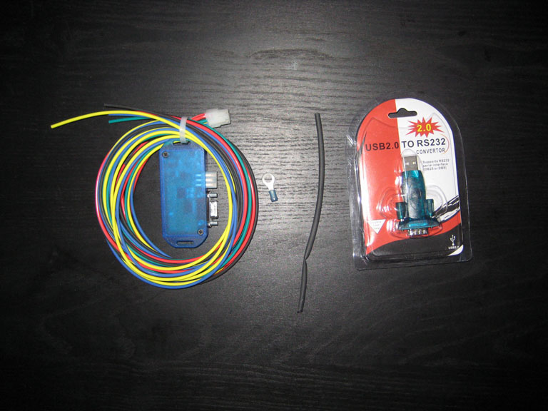
| The image above shows the parts of the N2MB WOT Box. What you see is just the WOT Box, 6 wires, some heat shrink and a terminal connector. The install is completely electrical, so there are not many parts to be described. Also included is a serial to USB adapter to be used for future software updates. | ||||||||||||
Part 1: Tapping the wires at the ECU
This section focuses on how to tap into the ECU harness to make the necessary connections. If you would prefer to tap each of these wires at the sensors themselves, you should check out the directions provided by N2MB. They will be updated shortly and can be found here: http://www.npcompleteperformance.com-a.googlepages.com/vw_audi_1.8T_installation_instructio.pdf |
||
 |
||
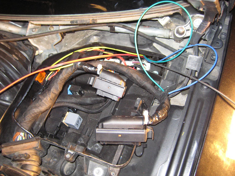
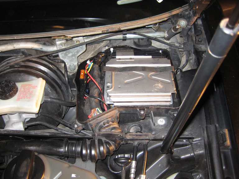
| The very first thing you need to do is access and remove the ECU. To do this you need to remove the battery tray, the driver's windshield wiper, etc. I have shown how to do this before in the ECU Removal Writeup | ||
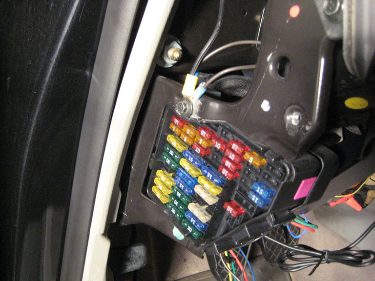
When you get to the ECU, you should be looking at something like this |
|
|
| At the ECU we will be looking to tap 3 lines. The three connections we are looking for are for the clutch pedal switch, the accelerator pedal switch and the ground line for injector number 4. N2MB provides directions on how to tap into these signals directly at the switches, however it is a much cleaner (and I thought easier) install to just do it right at the ECU harness itself. It was particularly easy for me because the security bolts on the ECU had been previously removed (as shown in the ECU Removal Writeup), so getting at the harness is quite trivial. | ||
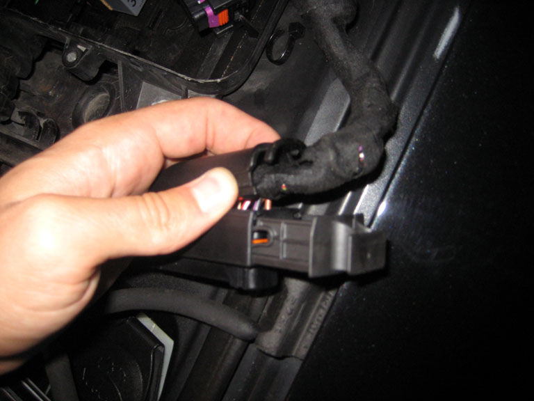
In order to tap the correct wires in the harness, you need to be able to see what pins the wires are going to. To do this, you need to remove the electrical tape from the harness, and remove the back side of the harness connector. To remove the backside of the harness connector, first clip the zip tie at the back end and then pinch the back of the connector as shown in the picture to the right. The back of the connector should pop up, and you should be able to easily remove it. Do this to BOTH of the harness connectors. |
|
|
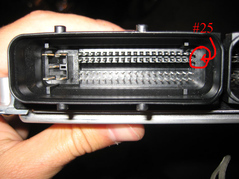
| When you remove the back of each of the connectors you will be able to look in the backside of the connector to see where each wire goes to a pin. A NOTE ON ECU HARNESSES: If you look at the backside of the harness connector itself, you will see that it clearly labels the pins in each corner of the harness. You will use these reference markings to find the pins which you need to tap. Check out the picture to the right to see the numbered markings. The picture is of the ECU side of the connection, but you will see the matching markings on the harness side. |
|
|
| As I said previously, we will need to locate and tap into 3 different wires at the ECM harness. Two of the taps will be made on the harness with the larger connector, and the other at the smaller connector. Since the WOT Box needs to be installed inside the cabin (not water proof), you need to run the WOT Box harness from inside the cabin up into the ECU box. I have shown you how to do this several times before. The procedure includes removing the driver's side kick panel and fishing the wires up into the ECU box. For more details, read the Podi Boost Gauge Writeup | ||
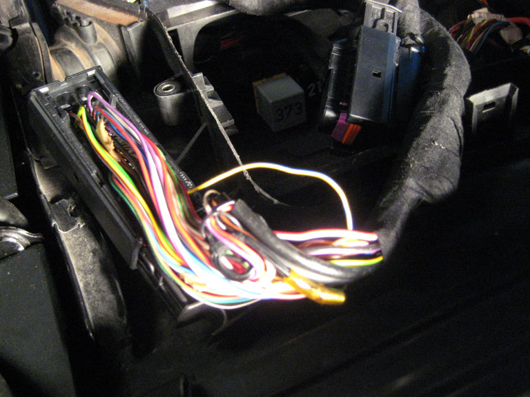
| The first wire we are going to connect is to the Accelerator Pedal Signal. This wire is located on PIN #35 at the ECU which is located at the larger harness. To find this wire just look at the back of the harness, find pin 25 and count over the correct number of pins to find the wire you need to tap. The wire will be Yellow/Blue in color. Separate the wire from the bundle, but BE SURE not to pull it out of the harness or pull the pin out. |
|
|
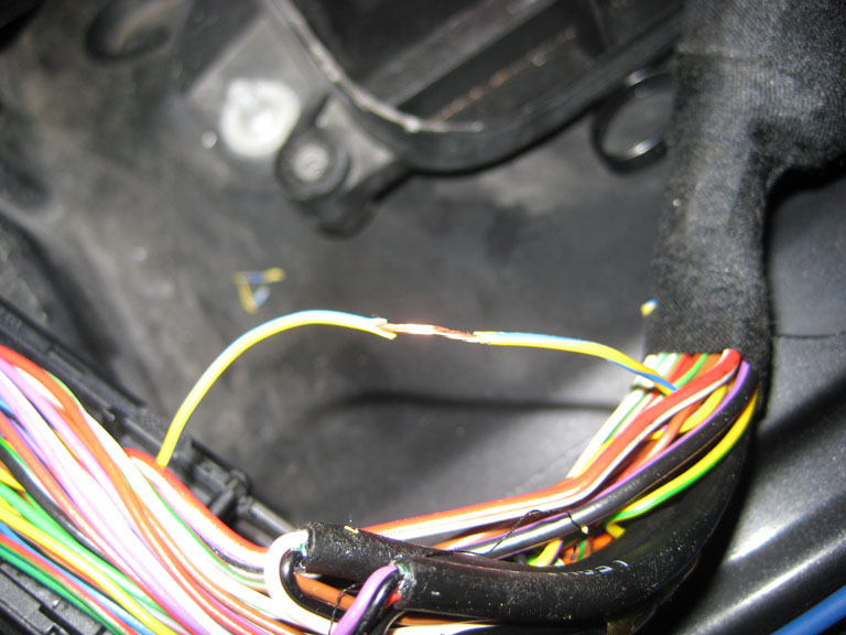 |
I would recommend stripping some of the insulation off without actually cutting the wire. I usually do this using a razor blade. It should look like what you see to the left. |
|
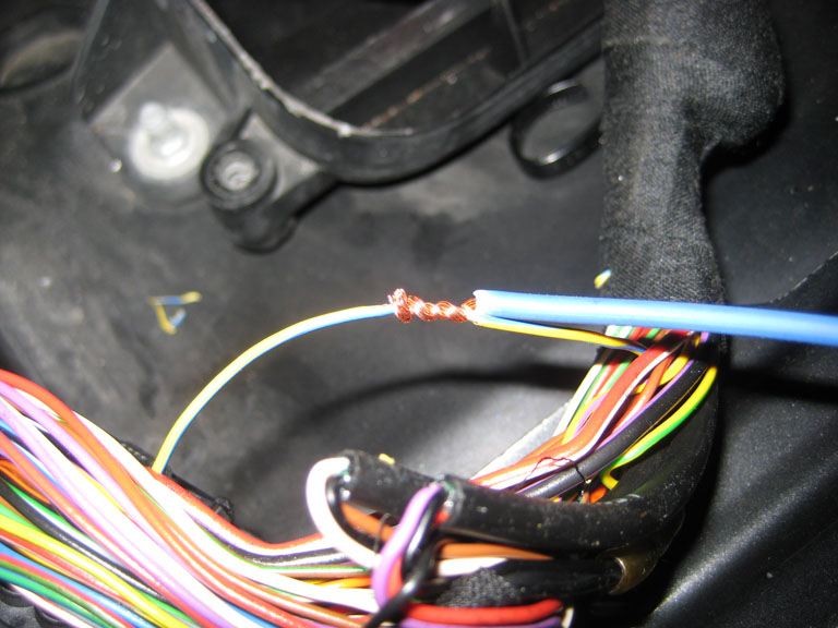
| The 18 AWG BLUE Wire from the WOT box needs to be stripped and connected to this Yellow/Blue wire from ECU pin #35. You should wrap the wires together and then solder them. | ||
 |
 |
|
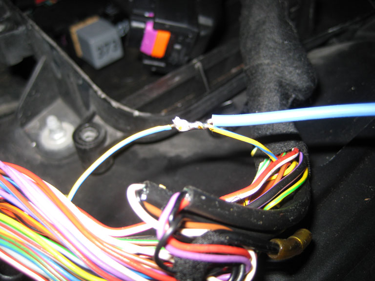
This same process needs to be repeated for the Clutch Position Sensor. The Clutch Position Signal is located at Pin #39 on the same harness and the wire color is Red/Green. The 18 AWG GREEN wire from the WOT Box needs to be connected to the RED/GREEN wire from Pin #39 on the ECU. SOLDER the connection when you are done. When this is done, you will have the two wires as shown to the right. |
|
|
| When you have connected these two wires to the larger of the two harness connectors, you can use electrical tape to wrap them up. Be sure to cover the connections completely as you do not want any shorts! | ||
When you have wrapped the connections, re-assemble the harness connector. It should look like this: |
|
|
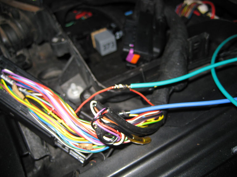
| The same exact procedure needs to be followed to make the connection to Injector Number 4. This connection, however, is located on the smaller of the two harnesses. You will find a Gray/Violet wire at Pin #88 on the small harness connector. The 18AWG Yellow Wire from the WOT Box needs to be spliced into this wire. Solder and wrap you connection when you are done. When you are done, it will look something like this. Don't worry, we will clean it all up in a bit. | ||
 |
||

Part 2: Splicing the Ignition Coils
| The next thing you need to do is splice into the ignition coils. To do this, you need to run the Red/Black wire from the WOT Box over to the coil packs. | ||
 |
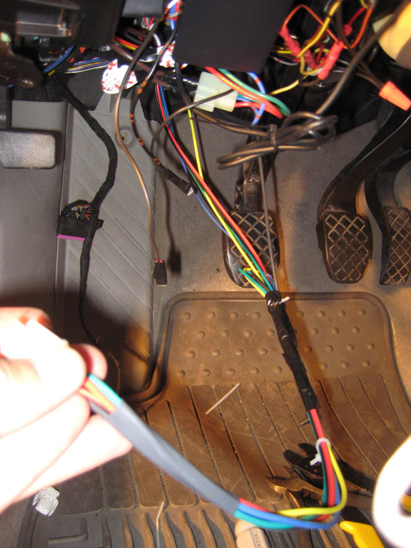
To get the Red/Black wires out of the ECU box and into the engine bay, just use a metal coat hanger to poke a hole through the rubber grommet. I showed this procedure once before on the boost gauge install. When you get the coat hanger through (check the picture no the left), just tape the end of the Red/Black wire to the coat hanger and pull it into the engine bay, behind the coolant reservoir. |
|
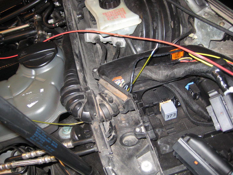
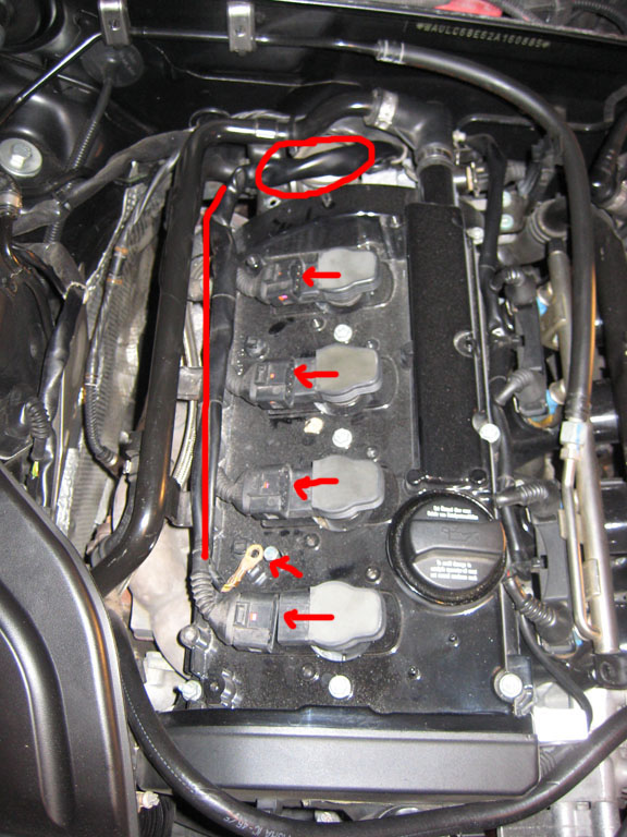
When you get the Red/Black wire into the engine bay, it is time to head over to the ignition coil harness (traced in RED in the picture to the right). You may have to remove your engine cover to access it. I would suggest disconnecting the four ignition coils and the ground - indicated by the arrows in the picture. I circled the area of the harness where we will be working. |
|
|
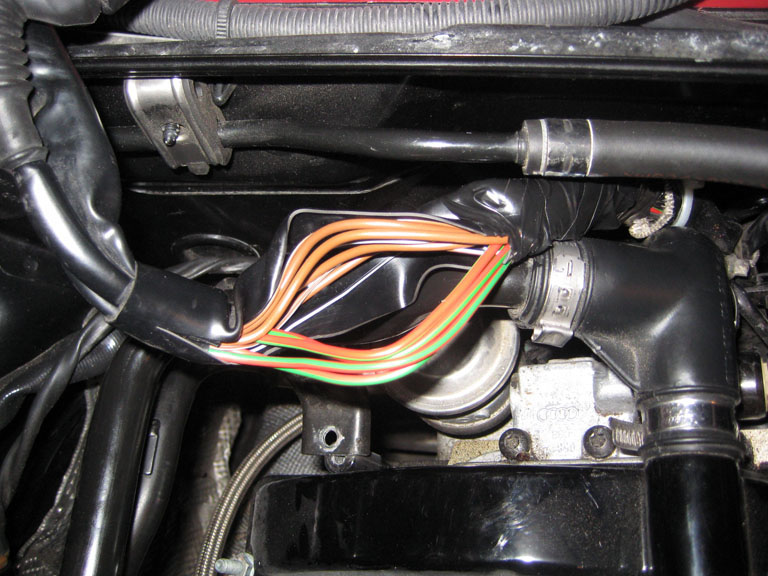
When you are ready, open up the wiring harness cover at the spot circled. You will see the following wires. You should see 4 RED/GREEN wires. I have separated them in the picture to the right These 4 wires are the power wires for each of the ignition coils. We will be cutting and splicing into these. |
 |
|
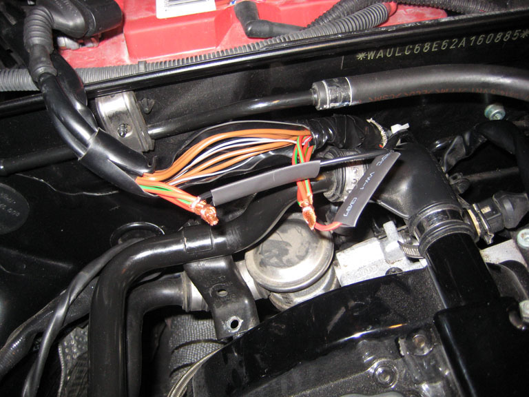
Cut the four wires and splice the 8 resulting ends. Run the RED/BLACK wire from the WOT box over to this area so you can work on it. 1) Splice the BLACK wire from the WOT Box and connect it to the four ignition lines going TOWARDS the ignition coils. Be sure to setup the shrink wrap so the splice can be covered after it is soldered 2) Splice the RED wire from the WOT Box and connect it to the four ignition lines going AWAY FROM the ignition coils. Be sure to setup the shrink wrap so the splice can be covered after it is soldered. You're setup should look like this: |
||
 |
||
SOLDER both of the connections, and cover them with shrink wrap. |
||
When the connections are complete, they should look like this: |
|
|
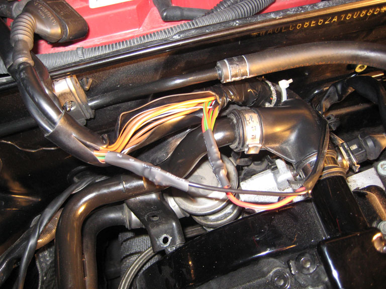
Tuck all the wires back into the harness and electrical tape the harness so everything is self contained. If you had to remove zip ties, replace them. Re-plug in the ignition coils, and re-connect the ignition coil grounding strap. It should looks like this: |
|
|
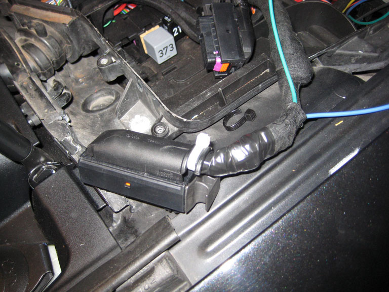
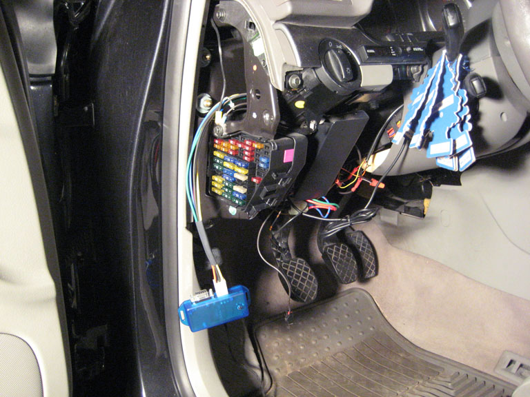
You can go back into the ECU box and clean up that area as well. Re-connect the harnesses, and tape/zip tie the WOT Box harness so it is organized. Here it is all buttoned up: |
|
|

Part 3: Connecting the Ground
Part 4: Using and Programming the WOT Box
|
|
||||||||||||||||||||||||||||||||||||||||||||||||||||||||
Usage: To use the WOT Shift feature, keep your foot fully on the gas and shift quickly using the clutch. Keep the gas fully depressed through the shift. The WOT Box will detect the clutch switch signal and briefly cut the ignition to enable an effortless shift. To use the 2-Step feature, fully depress the clutch. Next, fully depress the gas pedal to the floor. The engine will rev up and hold the RPM that you have set. Quickly release the clutch while leaving the gas fully depressed to launch the car. Programming The WOT Box comes preset for an automatic WOT Shift kill time. This means that the WOT Box will automatically adjust the kill time to your shift time, up to a maximum of 350 ms. If you would like manual control over the WOT Shift kill time, start the car and hold down the button on the module and wait for the LED to begin to blink. Using the chart below, find the number of blinks that corresponds to the kill time that you want to set. Setting 0 blinks will disable the WOT Shift feature and setting 1 blink will set the automatic kill time mode. When you have reached the number of blinks that match your desired setting, simply let go of the button. To confirm, the WOT Box will blink back out the setting you entered. The WOT Box comes preset for a 2-step RPM of 4000. To set the 2-Step RPM, repeat the same procedure described above, but keep the clutch down during the entire operation. This will signify to the WOT Box that you want to set the 2-step RPM and not the WOT Shift kill time. Use the second chart provided below to match up the desired RPM with the number of blinks. Setting 0 blinks will disable the 2-Step feature. Ignition Cut Time Chart - Set with clutch UP |
||||||||||||||||||||||||||||||||||||||||||||||||||||||||
|
||||||||||||||||||||||||||||||||||||||||||||||||||||||||
| 2-Step RPM Chart - Set with the clutch DOWN | ||||||||||||||||||||||||||||||||||||||||||||||||||||||||
|
||||||||||||||||||||||||||||||||||||||||||||||||||||||||